Tasks:
Based on the selected architectural design, you are to generate a Revit model. The model must be
compliant with LOD200 requirements, the Revit model must include at least 2 Revit Family components and we are required to create a blog or Facebook album for public access. The Work in Progress (WIP) print
screens and test renderings must be uploaded to the above online platform to show
progressive evidence of the working process. It will serve as a communication and mutual learning platform.
You are encouraged to visit your peers’ WIP and give constructive comments and suggestions.
GRID LINE:
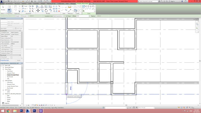
First of all, the vertical grid lines are drawn from downwards to upwards by numbers according to the dimension indicated on the reference's plan.
The horizontal grid lines are then indicated, it follows the flow the vertical grid lines, therefore horizontal lines are indicated by alphabets.
DIMENSION:
The dimensions are indicated for clearer drawings.
SLAB:
The floor slab are later sketched as seen the pink lines indicating the boundary, when finished click on the finish edit mode.
WALL:
Then according to the reference plan, walls are drawn.
For the walls height, the constrain can be altered for different walls to specify up to which level.
Slabs and walls drawing are repeated for ground floor and first floor.
New material are created by choosing edit type, details of specific material will be shown and can be altered by clicking on edit at "structure".
Finishes and structure are then indicated in terms of materials and thickness for each layers.
To have a better indication on plan, I chose "diagonal hatch" fill pattern for the grey masonry wall.
All the different genre of wall in my modeling of Flugel Haus with different materials and finishes layers.
And for curtain wall itself, just change from generic wall to "curtain wall: storefront" from the drop down menu from the left.
All walls' materials was defined for lower ground floor, then repeated for ground and first floor.
ROOF:
Boundaries were draw for both pitch and gable roof, slope was defined by selected degrees.
If the boundary line do not contribute to any slope level, uncheck the "define roof slope" at properties.
The roof are done by clicking on "finish edit mode".
Similar to the wall, I chose to re-create the materials and finishes layers for the roof.
WALL & ROOF:
With roof drawn, there's problem when walls can not seem to be attached exactly to the roof.
For the gable roof part itself, the front part are selected to be attached to the roof by clicking on "attach top/base" then click to the roof itself.
After the back part attaching to the pitch roof itself using the "attach top/base", the model looked more sleek.
CURTAIN WALL:
To match the mullions on the right, click on the "curtain grid" to to add on mullions on the left to align with the right side curtain wall.
When cursor is moved near to the curtain wall, the dashed line will indicate where the grid will be add in.
Mullions added following the curtain grid itself.
When specific mullion need to be deleted to accommodate doors,the mullions itself will be selected and unpinned.
After unpinning, delete the mullions, the grid segment will be deleted by clicking on "add/ remove segments".
Segments deleted.
CURTAIN WALL DOOR:
The specific glazed panel was tabbed to select to avoid selecting grids or mullions.
The panel was selected, then click on "edit type" in properties.
In type properties, click on "load" then libraries file will pop out.
Choosing the door folder, load the Curtain wall single glass door in.
Then, the door will be placed at the specific panel itself.
STAIRS:
Under "architecture" tab, choose "stairs by component", draw stairs in the middle axis, it will shows show many runs left to reach the next level.
Two separate runs created for the same stairs.
To add landing connecting both runs, click on the landing.
Then click on both runs, the landing will automatically connect the stairs.
For the equal stairs, just sketched according to the sides, the runs, rise and landing will automatically be created according to the sketch boundary.
It works for all the other levels as well.
SHAFT:
Slab created blocking the opening of the stairs therefore shaft is required to create the opening.
Shaft in structure tab was selected to sketch the shaft opening.
The boundary of shaft was sketched.
Once finished the shaft opening's height can be altered according to the openings that need to be cut open for stairs.
RAILINGS:
The railings were selected to change to different type of railings from the drop down menu at properties.
Path was sketched to locate the railings on the balcony.
The railings can also be changed from the drop down menu at properties.
FAMILY:
DOOR
Create new family, click on "new", then choose "metric door" for drawing the family.
Add the reference plane at plan and at the exterior view based on the dimension of the trim and inner frame.
Annotate the frame's width then locked to the reference plane.
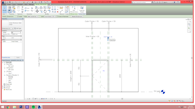
The reference plane were hold in place and annotated, then further locked in place, instance perimeter also added for the outer frame.
And in the plan view we need to fix the thickness of glass and frames.
After laying out all the length and width on the reference plan, select "label" on upper left, then add the perimeter for the thickness, check one "instance" instead of "type" as instance allow changing of dimension in models.
After adding the instance perimeter on the annotated dimension, lock them to the reference plane.
Then the extrusion are drawn based on the reference plane, with all the boundaries drawn, the outer frame created.
And for the frame that have been done, it is aligned with the reference plane, then locked.
For the outer frame, copy the bottom aligned frame to the top on plan, to create trims on both side of the door.
Lay out the reference plane to indicate the inner frame of the door.
Annotate the inner frame width, then lock to reference plane.
After the frames width are annotated, click on "label" on the upper left to add on instance perimeter to the inner frame to fix the width.
After adding instance perimeter, always try run with dragging the reference plane, then boundary for the inner frame is sketched.
The frame's lines are aligned to the reference plane and locked in place.
As for the panel itself, I am doing wood panel door with glass inserts. Therefore the glass in the middle itself, need to lay out reference plane.
Same as those before, reference planes are annotated then locked.
Perimeter is added for the door panel width, checking instance to fix the width but allows alteration for the door itself.
Instance perimeter was added then locked to reference planes.
After all the planes were added, boundary of extrusion of the panel was drawn, the all the lines were aligned and locked to reference plane.
Extrusion for panel are done, all locked to aligned reference plane and locked, the void created is where the glass inserts.
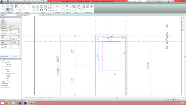
The glass inserts was later extruded then aligned and locked to reference plane.
From the plan view, the extrusion of panel and frame are out of place therefore it needs to align to the perimeter fixed for the thickness.
The panels and glass inserts are aligned to the thickness perimeter fixed previously, then locked on planes.
Then inner frame also fixed to the perimeter created previously, aligned and locked to reference plane.
Try run with the window itself with all the reference plane to make sure that all the constrain works for the door itself.
To be able to change the materials for the individual extrusion after loading into model, I added the material parameter for each of the components.
Then load into project.
WINDOW
To create a window family, click on "new" at family then choose the template "metric window".
Lay out all the reference line for the thickness of trim, inner frame and glass panel according to dimensions.
Annotate the thickness of frame and panel and lock to the reference plane.
Browse to the exterior view and lay out the reference plane for the trim, inner frame and panel.
Annotate the width of the inner frame and outer frame.
Then, set the perimeter for both the outer and inner frame to constrain when height and width are change in the model.
After the perimeter was set, lock it to the reference planes.
After all the constraints and start to extrude the outer frame then align and lock the extrusion to reference planes.
Same as the outer frame, the inner frame and glass panel are extruded, aligned and locked.
Annotate the dimension for the external frame that I had missed out just now.
Then add the perimeter to the dimensions and lock.
Lock the perimeter to the reference plane.
Align the external extrusion the the reference plane drawn previously, by clicking on "align" the to the reference plane, then only the extrusion line.
Same applied to all the lines that should align to reference plane.
FAMILY TO MODEL:
After importing the model, the family file for the window was dragged from the project browser to the plan itself to insert the windows.
To accommodate with the different dimensions of windows, I duplicated the family then click on the "edit type" in properties.
The duplicate family file was renamed to have a clearer identification.
Then the width and length was changed according to the design, sill height can also be changed in the properties tab to accommodate with design.
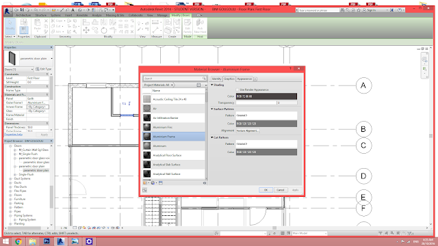 As I added materials' perimeter for panels and frame in the family file, when loaded in, it will allow you to change the material in the model itself.
After doors and windows were placed, those who opt for the same dimension and material application, I chose "match type properties" to eliminate the difficult way of adding materials one by one.
The door with materials were then selected after "match type properties", then only the other doors that follows its dimension and materials.
DONE.
Reflection:
Throughout the modeling process, from the most tiny detail like frames to walls, basically it require us to understand what should go first and which one next, from the tiny details like structure and finishes for the materials, we would require certain knowledge to put in the real materials and dimensions necessarily. This would also help us to understand more about the process, and throught creation of family components, we would need to understand the "formula" of how we do it, what's should be constrain and what should not be. It also helps a lot in understanding the buildability of a big model to small family component.






0 comments:
Post a Comment